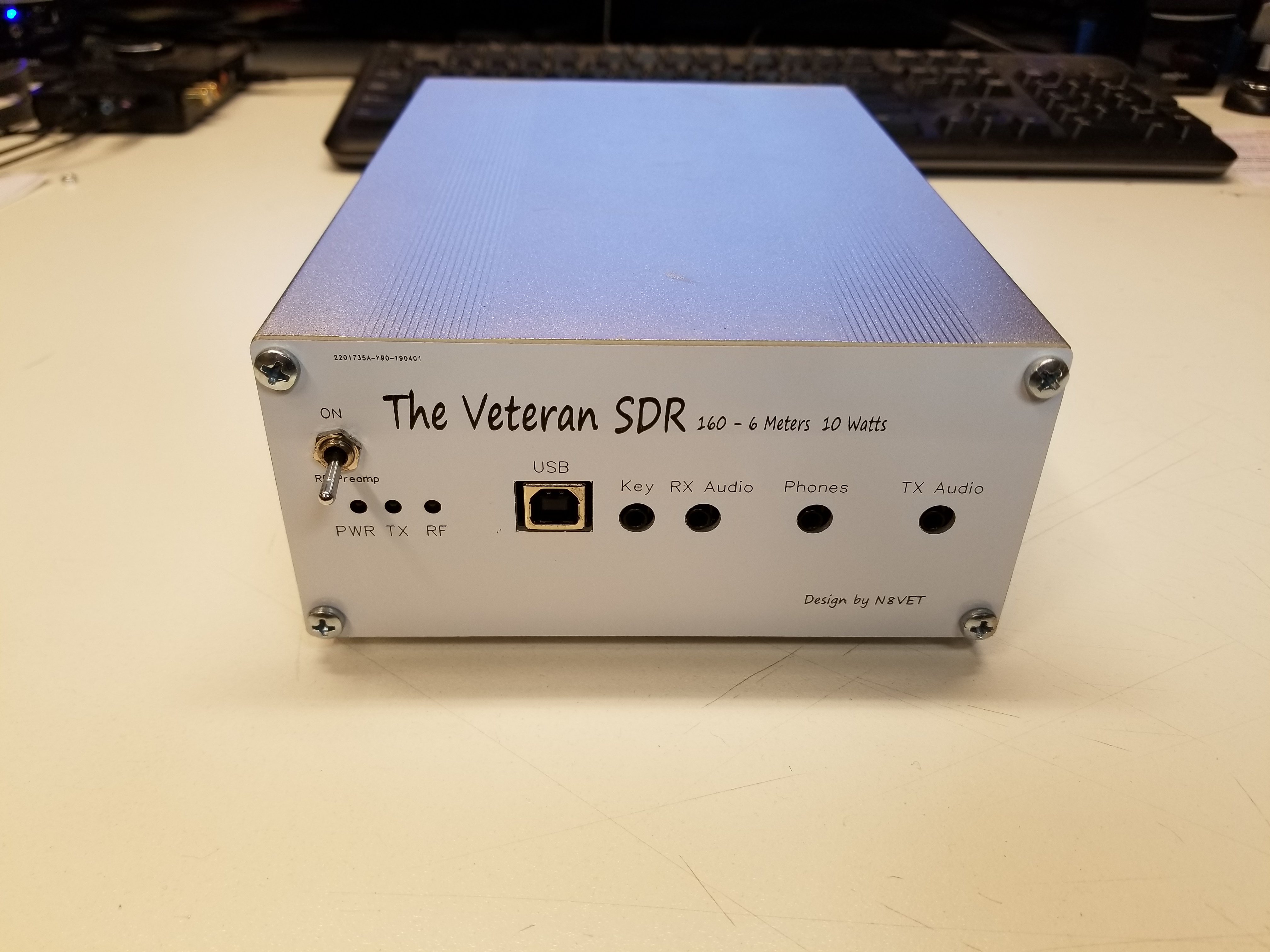


Introducing The Veteran SDR, a 160-6M radio with 10 Watts output.
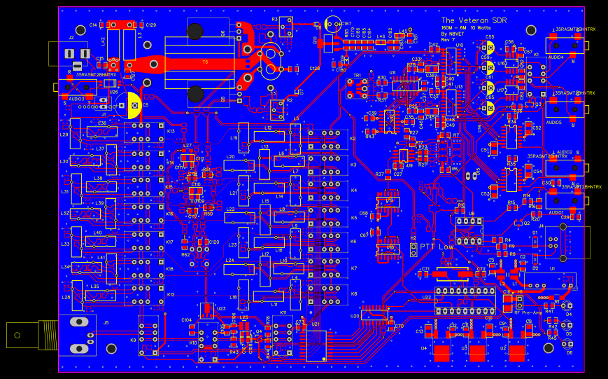
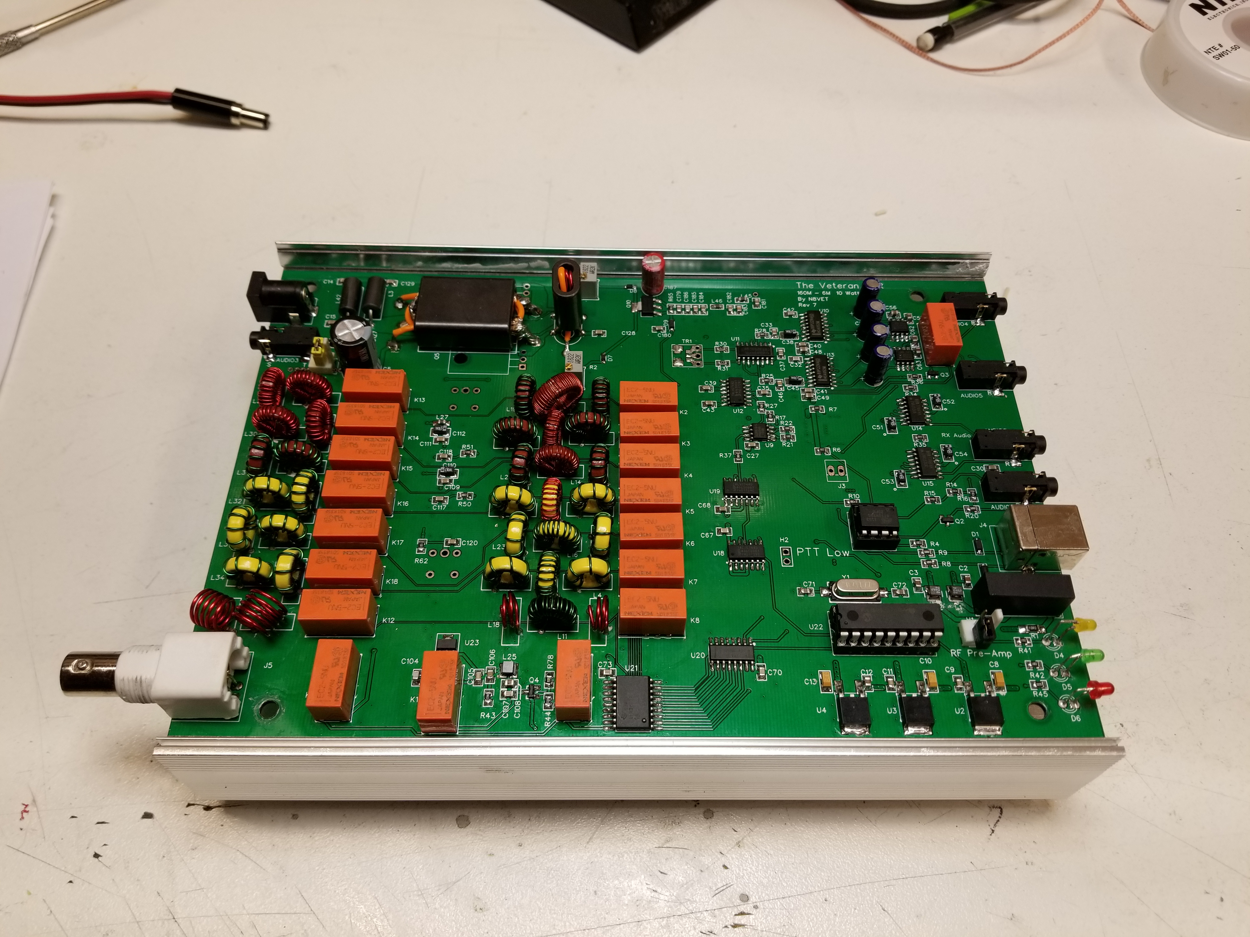
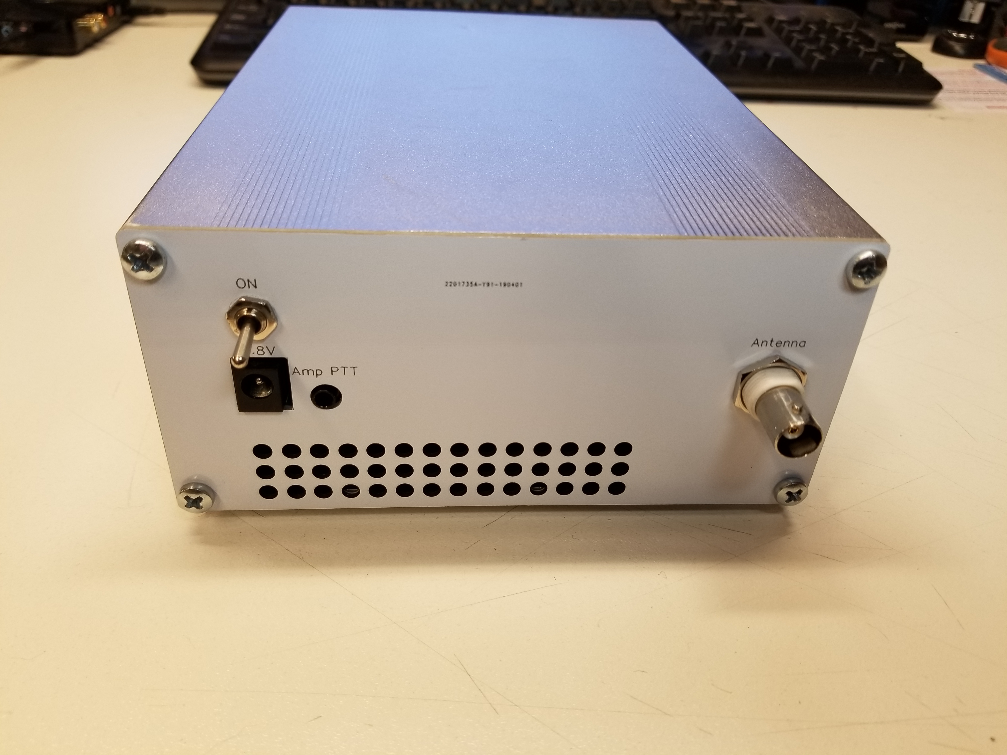
The Radio fits in a readily available 140x200mm enclosure. End plates are PCB materail with copper on both sides for RF shielding. This SDR is desgned to work with a computer sound card with a connection to a computer. Some features include: Head Phones Jack, PTT/Key input, PTT output(pulled low) and a switchable RF Pre-Amp. The PCB is a 4 layer board with inner ground plane and power plane for low current devices. The High current traces are external as for the amplifier. a 3 Amp resestable fuse is at the power input. Total current at 10W is around 2 Amps.
Generally all spuroius emissions are better than -50dbc. There are a few bands where the harmonics are -47dbc and I'm currently reworking the LPF's for those bands.
For increased oscillator stability there are provisions for a PTC to be attached to Si570 to help in warmup time and to stabelize frequency. Once warmed up and running WSPR my drift is typically 0 with a few 1's. The Si570 can be CMOS, LVDS or LVPECL. The only restriction is the I2C address needs to be hex 55. I have not been able to get other preprogrammed addresses to work.
As far as SDR host applications go there are many that will work. PowerSDR2.4.4 for homebuild rigs, HDSDR, GSDR and ke9ns PowerSDR with SDR-1000. Generally speaking any SDR application that works with a Softrocks is OK.
PCB in PDF format
Schematic in PDF
BOM in xlsx format